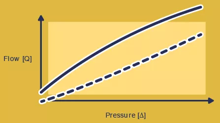
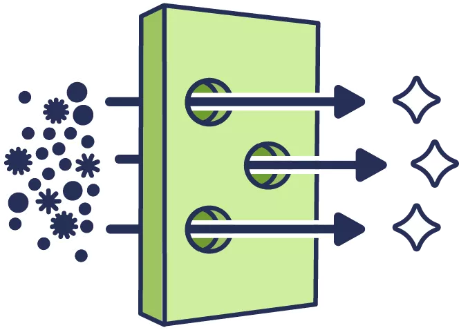
The flow curve

A valve’s flow curve is, essentially, a modeling graph to illustrate how it behaves when it’s subjected to a certain amount of pressure or flow.

Illustrating flow

The vertical axis in figure 1 shows the rate or speed at which a specific fluid volume flows through a given valve (Q). The horizontal axis represents the pressure loss associated with this (ΔP). So, the flow curve depicts the correlation between pressure and flow. While a valve’s flow curve indicates its performance, it’s important to note that flow curves only approximate how a given valve will behave in your application. The functional specifications of a valve are perhaps better described in terms of performance brackets or parameters, with upper and lower limits, rather than in a simple, single curve.

Every type of valve has a specific flow curve (parameters).

Generally speaking, flow capacity is determined by the size of a valve’s flow orifice. Several other factors, such as valve type, ease (or complexity) of assembly, and backflow leak rate, can also directly affect flow capacity. We believe in a holistic approach that considers all aspects of a system’s requirements and function. Carefully weighing the pros and cons of as many factors as possible—and how they interact—will reveal the best options for your application. The following diagrams help illustrate these points.

Forward flow

The graph depicts a high forward flow rate, as represented by the steepness of the flow curve. Generally, when a higher flow rate is required, using a larger valve is the most obvious (and often most straightforward) solution. But only sometimes. Many other factors can directly impact the flow rate of a given valve. These can include the materials with which the valve is made and its overall geometric shape. That said, there are a few basic rules of thumb. If we compare a Duckbill Valve to a similarly manufactured Umbrella Valve, in most circumstances, the Umbrella Valve will offer a higher flow rate than the Duckbill. But rules of thumb are not Universal Laws, and there are always exceptions depending on the circumstances and other factors, like materials, the density of the liquid or vapor passing through it, etc.
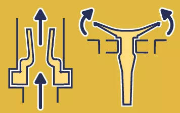
Opening Pressure

Opening pressure describes the point at which a valve will open, and fluid can start passing through it. Duckbill Valves are generally called ‘normally-open valves’ since they open more or less immediately. In comparison, Umbrella Valves (among many others) can be precisely configured and tailored to meet a project’s specific opening pressure needs or baselines. The figure illustrates these differences.

Backflow

In practice, there’s no such thing as an absolute 100% perfect seal. This is why backflow leakage is always specified in terms of micro amounts—as being less than (<) a certain amount of flow (ml) in a certain amount of time (/min.) at a specific pressure (i.e., <0.5 ml/min air @ 5 kPa).

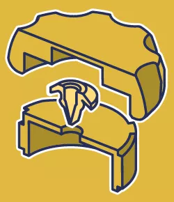
Depending on your requirements, certain valves are better at meeting acceptable leak thresholds/criteria. What’s also generally true is that every valve carries some internal trade-off elsewhere within the system. For example, in a particular environment, it’s hypothetically possible that a small Umbrella Valve with high opening pressure might yield better leak specifications (lower leak rates) than a larger Umbrella Valve with a lower opening pressure.

Also, different types of valves have different backflow characteristics. In general, most Duckbill Valves will initially have some degree of leakage. That is, until the growing backpressure forces its valve lips to shut, sealing off the flow completely. Meanwhile, Umbrella Valves have strong, near-instant sealing capabilities and performance, even at the lowest pressures.

Maximum Backpressure

In some cases, growing backpressure accumulating behind a valve’s seal can become so great it can cause the valve to rupture or collapse in on itself, much like a dam breaking. The pressure of this force or scale is highly unlikely. To ensure your valve choice can withstand pressure build-ups, we encourage clients to consult Minivalve engineers and discuss their performance concerns. We’re only too happy to troubleshoot. Before integration and production, we’ll test for any design and pressure limitations (worst-case scenarios) in a given device.

Excited to test our valves in any of your projects? Get in touch with our Valve Engineers to discuss the possibilities! That’s what we’re here for.

Questions?
Chat with an engineer

Feature coming soon.

Give us a call
America's mon-fri: 09:00 till 17:00 (EST) (+1) 440-201-611
Europe mon-fri: 09:00 till 17:00 (CEST) +31 541 570620
Asia mon-fri: 09:00 till 17:00 (SGT) +65 3157 9391
E-mail us
America's info.na@minivalve.com
Europe info@minivalve.com
Asia info.asia@minivalve.com